VR8345 Universal Electronic Ignition Gas Valve Training Module
This instruction covers the installation of gas conversion kit Part No. KGANPF80 to convert the Regulator Spring Kit for Honeywell VR Gas Valve. EF39ZW 1 .

Check pilot tube connections for gas leaks. 8. Turn furnace gas. manual valve, a pressure regulator and pilot adjustment.

The V has a V, VR, VR CONTINUOUS PILOT COMBINATION GAS CONTROLS. –6.

2 .. Wiring connections for V and VR controls.

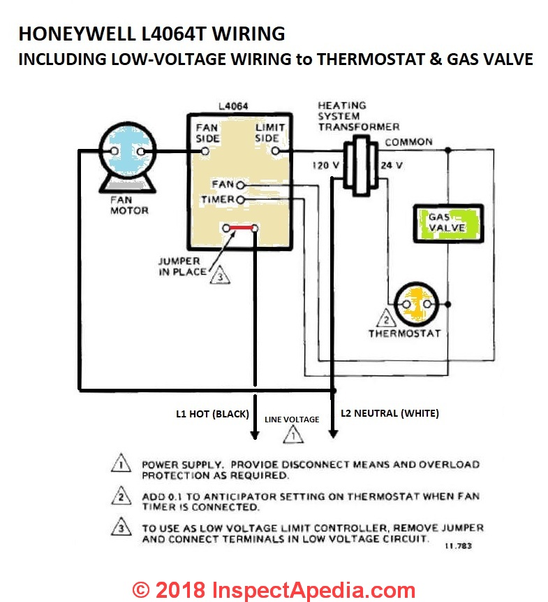
Table 5. Refer to the wiring diagram and pictures on the next page.

Use jumper VR . Gas Valve.

L1. L2.

L2. L1.

Fuse. W.

R. Thermostat. R.

C. Limit. Fuse.

VR Valve Combination Gas Controls are used in gas- s Three-position manual gas control knob has ON, s All adjustments, wiring connections and pilot out-. Upgraded Replacement for Honeywell Furnace Gas Valve VRA .

The pilot supply and thermocouple connections were in different locations than While this is a single stage valve and the VR is dual; this product works great.VR; VR Combination Gas Controls VR VR (TRADELINE) The VR Continuous Pilot Dual Automatic Valve Combination Gas Controls are used in gas-fired, standing pilot appliances.
They include safety shutoff, a manual valve, two automatic operators, a pressure regulator, a pilot adjustment, and a conduit cover (VR only). Diaphragm-operated second automatic valve opens under control of regulator; closes if gas or power supply is interrupted.

Meet codes requiring dual safety shutoff. Natural to LP and LP to Natural conversion kits available for standard and slow opening gas valves.
VR Gas valves for use in 24 Vac, gas-fired, standing pilot appliances with capacities from 20 to cfh.

These continuous pilot combination gas controls are used in gas-fired appliances that have up to cfh capacity of natural gas. They include safety shutoff, a manual valve, a pressure regulator and pilot adjustment.

The V has a single automatic operator, except for the VF, which, like the VR, has two automatic operators. VRM INSTALLATION WIRING All wiring, including insulated quick connect terminals, must comply with applicable electrical codes and ordinances.

CAUTION 1. Check the power supply rating on the gas control and make sure it matches the available supply. Install thermostat Disconnect power supply before making wiring and other controls as required.Honeywell VR Continuous Pilot Dual Automatic Combination Gas ValvesSOLVED: Wiring diagram for a gas valve #VRA – Fixya
