Further information can be found in the PowerFlex user manual UM of . The precise knowledge of the operating instructions, wiring diagram, and.
PowerFlex 525 Series Keypad Navigation
Answer. This document is intended to provide the basic Parameters settings and wiring to a standalone PowerFlex AC drive.

It is setup in different sections. – PowerFlex / drive: Wiring and Settings for Analog Output Further information including wiring diagrams can be found in the PowerFlex.

The examples and diagrams in this manual are included solely for illustrative purposes. .. Added note to PowerFlex I/O wiring example for pulse train input.

The PowerFlex drive provides maximum flexibility and . C1.

C2. Safe- Torque-Off.

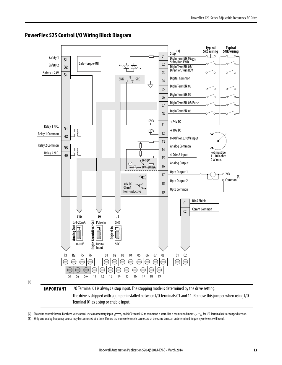
PowerFlex Control I/O. Wiring Block.

Diagram. See the PowerFlex Control I/O Wiring Block Diagram on page 38 and PowerFlex Control I/O Wiring Block Diagram on page 42 for location.

• Configure the other drive parameters needed for the drive analog and digital I/O to work correctly.
and so on).1/5(1).

Wiring Block Diagram. 4 Rockwell Automation Publication TDE-EN-E – July PowerFlex Series AC Drive Specifications Communications The PowerFlex drive allows for configurable closed loop control with an optional encoder card for either speed or.

Feb 19, · The new Allen-Bradley® PowerFlex® AC drive from Rockwell Automation delivers an innovative modular design that is remarkably versatile and . Nov 17, · Eric, when I ordered a a while back, my distributor over here said AB doesn’t have a printed manual.

I can only shake my head at whoever at AB . Rockwell Automation Publication QSA-EN-E – March PowerFlex Series Adjustable Frequency AC Drive.

PowerFlex Control I/O Wiring Block Diagram.Rockwell AutomationRockwell Automation