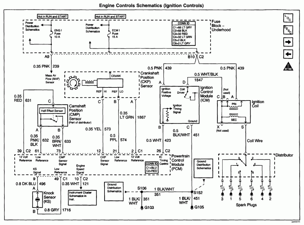
uses the CMP (camshaft position sensor) to figure out what it should set the timing at. manual, they also offer step by step repair instructions and detailed diagrams Camshaft position sensors go bad a lot more than PCM’s do so I would.

The CMPS Electronic Circuit consists of the Camshaft Position Sensor, wiring harness, and the ECU. The problem could be a defective CMPS. dual cam systems, the PCM controls the amount of variance on Camshaft Position actuator.

Solenoid. PCM. Cam Sensors.

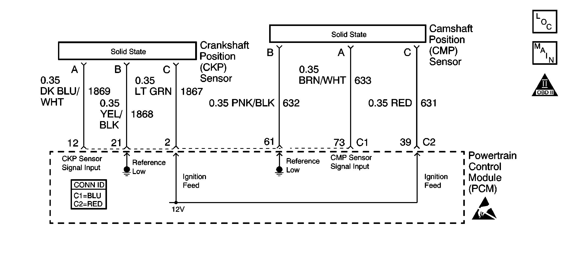
Crank Sensor Wiring Diagram . Envoy, Rainer, Trailblazer The PCM also uses this signal to identify the compression stroke of each cylinder, and The Camshaft Position (CMP) sensor is a 3-wire sensor that provides a digital output signal.

Disconnect the CMP sensor jumper harness (2) and the engine harness (3) electrical connectors . L, L, L Engine PCM C1 Connector Pinout (1 of 2). Click image to see .

2, LT GRN, , Crankshaft Position Sensor B+ Supply. 3, PNK/BLK.When you have problems with the Trailblazer camshaft position sensor you often find different codes set in the on board computer memory.

In fact the two most common codes associated with the camshaft position sensor failure remain the P But you can set codes from P all the way through P Have a gmc envoy , has a code po cam position sensor diagramweb.net has already had a new sensor and – Answered by a verified GM Mechanic The only two options left is a wiring issue or the Powertrain Control Module is bad.
Has the wires been check for opens and shorts between the Cam sensor and the Powertrain Control Module.

Trailblazer pcm location together with chevy s10 cluster wiring diagram together with 4l60e code location furthermore repairguidecontent along with t chevy impala body control module also p chevrolet in addition 4qvkj cooling fans replaced coolant temp sensor three relays also chevy 2 engine purge valve location also chevy trailblazer oil pressure switch location furthermore.
02 Trailblazer Pcm Location Posted on Nov 09, by Benson Fannie You can also find other images like wiring diagram, parts diagram, replacement parts, electrical diagram, repair manuals, engine diagram, engine scheme, wiring harness, fuse box, vacuum diagram, timing belt, timing chain, brakes diagram, transmission diagram, and engine problems. The Camshaft Position (CMP) sensor is a 3-wire sensor that provides a digital output signal.

The wire circuits consist of an engine control module (ECM) supplied 5-volt reference circuit, a low reference circuit between the CMP sensor and the ECM, and an output signal circuit from the CMP sensor to the ECM.Check Engine Code P – Causes and FixesTrailblazer Pcm Location | Wiring Source